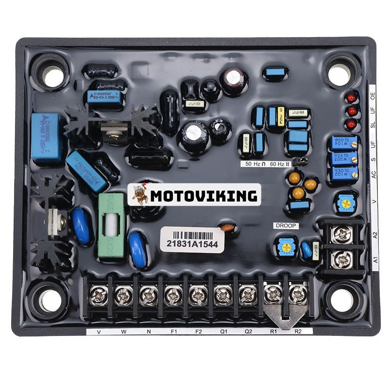
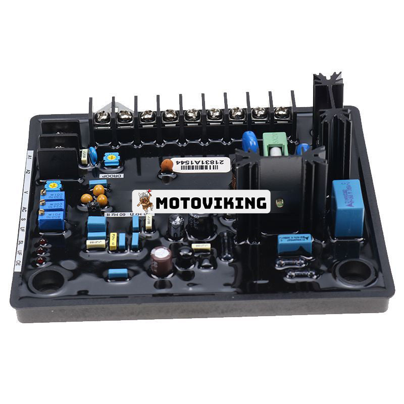
Voltage regulator AVR R150 for Leroy Somer
Article number:
Leroy Somer voltage regulator 5014127
Leroy Somer voltage regulator 40022682
Applications:
The R150 is used on the following Leroy Somer generators:
TAL046 A, TAL046 B, TAL046 C, TAL046 D, TAL046 E, TAL046 F, TAL046 G, TAL046 H, TAL046 J
TAL047 A, TAL047 B, TAL047 C, TAL047 D, TAL047 E, TAL047 F
TAL049 B, TAL049 C, TAL049 D, TAL049 E
Specification:
1) Input detection
- Voltage: 240 V AC ±10% for 1 phase, 380 V up to 480 V AC ±10% for 3-phase, 2-wire sensing AVR Senses the true average of line to line waveform. Use Resistor (SMD) network for trouble-free sensing and control of sensed voltage/regulation.
2) Input power
- Voltage: 415V for 3-phase and 240V for 1-phase
- Frequency: 50/60 Hz
3) Output power
- Voltage: 105 V DC at 240V AC input
- Current:
• 6 Amps DC Continuous
• 8 amps for 30 sec. (when permitted by field resistance)
4) Operating temperature: -20ºC to +70ºC
5) Storage temperature: -40ºC to +80ºC
6) Voltage adjustment: min ± 10% of rated voltage.
7) Stability adjustment: adjustable to get steady state Stability good transient response.
8) Remote voltage adjustment: to obtain ±10% of the set terminal voltage (with 2W / 2.5W, 1 Watt pot).
9) Droop for parallel operation: 4% drop for 5 Amp from the «U» phase.
10) Auxiliary input A1 & A2: ±4.5V DC gives a change in the terminal voltage of ±10%.
11) Under frequency roll-off adjustment: available under 46 Hz for 50 Hz and under 56 Hz for 60 Hz.
12) Voltage build-up: ≥ 2 Volts (LN)
13) Voltage regulation: ± 0.8% at AVR terminals.
14) Thermal drift: ± 1% for 30ºC temperature change.
15) Response time: less than 50 milliseconds.
16) Closed loop response: typically 0.5 sec to recover to 98% of the set voltage for a field strength ratio of 1:2.
17) Loss of sense protection: the voltage should collapse when the sense circuit is open.
18) Over-excitation protection: 10V DC to 85V DC. Setpoint: 60 V DC
19) Fuse for protection: 6 amps, 240 volts AC.
20) All potentiometers: multi-turn except Droop pot (Droop single-turn)
21) Potentiometer sealing: except for the V – trim pot, all pots are sealed.
22) Frequency cut-off indicator: LED included (UF).
23) Sense Loss indicator: LED included (SL).
24) Over-excitation indicator: LED included (OE).
25) Protection of the devices: Suitable RC Snubber shall be provided for the device used to protect it from over voltage.
26) Potting/Encapsulation details: the components of the AVR should be fully encapsulated with a suitable PU resin mixture to absorb transients/vibrations during operation.
27) Generator excitation details: (typical)
- Full load:
• Excitation voltage: 40 to 50 volts
• Excitation current: 2.5 to 5.0 amps
28) Terminal marking: see drawing
29) AVR testing: Burn-in test, thermal cycling, static test, voltage variation check, build-up test, FRO check, stability check, QDC check, remote voltage control, DC input voltage check.
Spare part for Leroy Somer.
Part/Replacement Number: PART NUMBER, 5014127, 40022682, APPLICATIONS, GENERATORS, SPECIFICATION, RESISTOR, PROBLEM FREE, CONTROL, REGULATION, FREQUENCY, OUTPUT, CURRENT, CONTINUOUS, OPERATING TEMPERATURE, STABILITY ADJUSTMENT, ADJUSTABLE, STABLE, STABILITY, TRANSIENT RESPONSE, PARALLEL, ROLL-OFF, ADJUSTMENT, AVR TERMINALS, THERMAL, RESPONSE TIME, MILLISECONDS, TYPICAL, COLLAPSE, POTENTIOMETERS, MULTITURN, DROOP-SINGLE TURN, TRIM POT, LOSS INDICATOR, UNITS, SNUBBERS, UNIT, POWDERING, ENCLOSURE DETAILS, COMPONENTS, ENCLOSED, PU RESIN MIXTURE, ABSORB, TRANSIENTS, VIBRATIONS, EXCITATION DETAILS, GENERATOR, DRAWING, AVR TESTING, CYCLING, STATIC, BUILD-UP TEST, FRO CHECK, STABILITY CHECK, QDC CHECK.
Please contact us if you need help verifying compatibility or finding similar parts.